
MC4 Connectors Explained
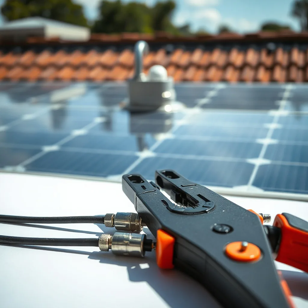
MC4 connectors are the small but essential components that link solar panels into reliable electrical circuits. Their locking, weather-resistant design helps photovoltaic systems operate safely through heat, rain, dust, and years of outdoor exposure.
Although these connectors appear simple, incorrect pairing or installation can create resistance, overheating, electrical arcing, and even fire. Understanding their design, ratings, compatibility, and assembly requirements is therefore important for installers, system owners, and maintenance teams.
The name originally referred to a four-millimeter contact connector developed by Multi-Contact, now known as Stäubli. Today, “MC4” is often used broadly, but not every similar-looking product is technically or safely interchangeable.
MC4 Connectors Fundamental Concepts and Definitions
MC4 connectors are single-contact electrical connectors used primarily on the direct-current side of solar installations. They connect module leads, extension cables, combiner boxes, and inverters, allowing panels to be arranged in series or parallel. Their plug-and-socket structure includes metal contacts, insulated housings, seals, and locking tabs.
A typical connector contains a crimped metallic contact that carries current. The surrounding plastic housing provides electrical insulation and mechanical protection. An internal sealing ring limits the entry of water and dust when the connector is correctly assembled and fully mated.
The connectors are gendered, but their terminology can be confusing. A housing that appears male may contain a female metal contact, while the female-looking housing may hold the male pin. Installers should identify components using manufacturer documentation rather than visual assumptions.
Voltage and current ratings depend on the exact model, cable size, operating temperature, and certification. Modern products may be rated for photovoltaic systems operating at 1,000 or 1,500 volts DC. Current limits commonly range from around 30 to 50 amperes, but the manufacturer’s data sheet always takes priority during [photovoltaic system design].
Design History Standards and Practical Uses
Early photovoltaic installations often relied on junction boxes and field wiring that demanded more installation time. As the solar industry expanded during the 1990s and 2000s, standardized plug-style connections made module installation faster and reduced direct exposure to live contacts. MC4 connectors eventually became a familiar feature of grid-connected and off-grid arrays.
Their locking mechanism is particularly important. Once two compatible connectors are fully inserted, flexible tabs secure the connection and normally require a suitable unlocking tool for separation. This feature reduces accidental disconnection but does not make the connector safe to open while carrying electrical load.
Quality connectors are tested against relevant safety and performance standards. IEC 62852 addresses connectors used in DC applications within photovoltaic systems, while UL 6703 covers photovoltaic connectors in North American markets. Local electrical rules, including applicable provisions of the National Electrical Code, may also regulate connector use, accessibility, and installation.
In practical terms, MC4 connectors appear on rooftop arrays, utility-scale solar farms, portable power stations, boats, recreational vehicles, and remote pumping systems. A residential installer might use an approved extension lead to reach an inverter, while a solar farm may use thousands of connectors across long module strings. In both cases, accurate [DC cable sizing] remains essential.
Not all products marketed as MC4-compatible are approved for mixed mating. Two connectors may physically fit while using different contact materials, tolerances, seals, or locking designs. Such differences can increase contact resistance and weaken environmental protection. Recognized testing bodies and manufacturers generally advise mating only connector pairs specifically evaluated and listed for use together.
Connector performance also depends on temperature. Electrical resistance produces heat, and high ambient temperatures can reduce allowable current. Modules installed close to dark roofs may experience conditions far hotter than the surrounding air. Designers should therefore examine temperature correction factors instead of relying only on a prominent current rating.
Environmental protection ratings require context. A connector may carry an IP67 or IP68 designation, but that protection usually applies only when it is correctly assembled and mated. An open connector left in rain, placed on wet ground, or contaminated with dust may no longer provide the expected seal.
Series and parallel arrangements create different demands. Series connections increase string voltage while current remains broadly similar. Parallel connections increase current and may require branch connectors, overcurrent protection, and carefully coordinated conductor ratings. These decisions belong within a complete [solar panel wiring] plan rather than being treated as connector choices alone.
Expert Recommendations and Installation Tips
– Use one approved connector system. An installer should select matching housings and contacts from the same manufacturer and product family unless documented certification specifically permits mixed mating. Similar dimensions do not establish electrical compatibility.
– Confirm every technical rating. The connector’s voltage, current, cable range, insulation diameter, pollution category, and temperature limits should suit the installation. A 1,500-volt label alone does not guarantee that every attached cable is suitable for that voltage.
– Choose genuine photovoltaic cable. Solar cable is designed to tolerate ultraviolet exposure, moisture, heat, and mechanical stress. Ordinary indoor wire can deteriorate outdoors even when it initially fits inside the connector gland.
– Strip insulation to the specified length. Removing too little insulation may prevent full contact insertion. Removing too much can expose conductor strands or interfere with sealing. The manufacturer’s measurement should be followed precisely.
– Use the correct crimping tool and die. Pliers or generic crimpers can deform the contact unevenly. A controlled, gas-tight crimp limits resistance and withstands mechanical pulling. Professional tools also help produce repeatable results across large installations.
– Inspect conductor strands before crimping. Strands should not be cut, oxidized, folded backward, or left outside the contact barrel. Damaged conductors reduce the effective cross-sectional area and can create concentrated heating.
– Perform a gentle pull test. After crimping, the installer should confirm that the conductor is mechanically secure. Excessive pulling should be avoided, but a controlled test can reveal an incomplete crimp before the connector enters service.
– Tighten the cable gland properly. The gland must compress the seal around the cable jacket without damaging it. Under-tightening permits moisture entry, while excessive force may distort seals or crack lower-quality housings.
– Never disconnect under load. Direct-current arcs can persist longer than alternating-current arcs. The system should be isolated through the approved shutdown procedure before connectors are opened, in line with established [solar installation safety] practices.
– Document and inspect the installation. Records should identify connector brands, tools, cable sizes, and string locations. Thermal imaging and visual inspection can later reveal hot spots, discoloration, loose routing, broken locks, or signs of moisture.
Cable management deserves equal attention. Connectors should not hang under their own weight, rest on roofs, or remain submerged in pooled water. Appropriate clips and supports reduce strain while keeping the connection away from abrasive surfaces and sharp bends.
Installers should also keep connector ends clean during construction. Dust, oil, moisture, and building debris can contaminate contact surfaces. Protective caps supplied or approved by the manufacturer are preferable to improvised tape, which may trap moisture or leave adhesive residue.
Before commissioning, polarity should be verified with a suitable meter. Reverse-polarity connections can damage equipment even when the plugs fit correctly. Open-circuit string voltage should also remain within the operating limits established during [inverter selection].
Routine maintenance does not normally require opening sound connections. Unnecessary disconnection can wear contacts, damage locking tabs, or introduce contamination. Inspection should focus first on cable support, housing damage, discoloration, unusual heat, and evidence of water entry.
Frequently Asked Questions About MC4 Connectors
Are all MC4 connectors compatible?
No. Many connectors share a similar shape, but physical fit does not prove tested compatibility. Contacts may differ in coating, spring pressure, dimensions, and metal composition. Seals and housings may also respond differently to heat and aging.
The safest approach is to use matched components from one manufacturer and product line. If different products must be paired, the installer should require explicit documentation showing that the combination is approved by the manufacturers and accepted under relevant certification and local rules.
Can MC4 connectors be installed without a special tool?
They can sometimes be pushed together by hand, but proper assembly requires more than mating the housings. The metallic contact must be crimped with the tool and die specified for the connector and cable. Cable-gland wrenches may also be necessary to achieve the required seal.
Using ordinary pliers can produce a connection that looks acceptable while hiding gaps or damaged strands. These defects raise resistance and may become dangerous only after months of thermal cycling.
Are MC4 connectors completely waterproof?
They are better described as weather-resistant when correctly assembled and mated. Their published IP rating applies under defined test conditions, not every possible outdoor situation. Compatibility, cable diameter, seal condition, and gland torque all influence protection.
Open ends should never be assumed waterproof. They should be capped and stored away from rain, condensation, dirt, and standing water until the final connection is completed.
Can a connector be reused?
The answer depends on its condition and the manufacturer’s instructions. A housing may sometimes be remated if it has not been damaged or contaminated. However, a previously crimped contact should not simply be transferred to another cable.
Any connector showing cracks, corrosion, softened plastic, broken locking tabs, or heat discoloration should be replaced. When uncertainty exists, replacement is usually less costly than investigating a future system fault.
What causes an MC4 connector to overheat?
Common causes include poor crimping, incompatible mixed mating, damaged conductor strands, incomplete insertion, corrosion, contamination, excessive current, and loose cable glands. Heating can worsen over time because repeated expansion and contraction may further weaken an already defective connection.
Thermal imaging can identify abnormal temperature differences during operation. A hot connector should not be handled or disconnected under load. Qualified personnel should isolate the circuit before examining or replacing it.
How long do MC4 connectors last?
A high-quality connector installed under approved conditions is designed to support the long service life expected from a photovoltaic system. Actual durability depends on ultraviolet exposure, temperature cycles, humidity, chemical exposure, mechanical strain, and installation quality.
A connector cannot be judged by age alone. Periodic inspection, system monitoring, and attention to unexplained power losses provide a more reliable picture of its condition.
Can homeowners repair damaged solar connectors themselves?
Solar strings may carry hazardous DC voltage whenever light reaches the panels. Switching off the inverter does not automatically eliminate voltage in every cable. For that reason, repair should normally be completed by a trained technician who understands isolation, polarity testing, arc hazards, and local electrical requirements.
A homeowner can report visible cracking, hanging cables, unusual odors, or signs of overheating. The person should avoid touching, opening, or taping over a suspect connection.
Conclusion
MC4 connectors make modern photovoltaic installations faster, modular, and more resistant to outdoor conditions. Their compact appearance, however, can hide the importance of precise cable preparation, approved component matching, correct crimping, and careful system design.
The most frequent problems do not arise from the connector concept itself. They usually result from mixed brands, unsuitable tools, poor workmanship, contamination, mechanical stress, or disconnection under load. Each of these risks can be reduced through documented installation procedures and qualified inspection.
When properly selected and assembled, MC4 connectors provide dependable service for residential, commercial, and utility-scale solar arrays. Treating them as engineered electrical components—not simple plastic plugs—protects equipment, workers, property, and long-term energy production.
For every wiring and mounting article, see the hardware topic guide.
Related Posts

Leave a Comment
Your comment will be published after it has been approved. Please send comments that do not contain slang words.